Evaluating E-paper Display Design Considerations with the EXT3
20 Sep 2021
Faced with the need to extend battery life, many OEMs within the electronic industry are migrating away from the use of conventional display technologies, and looking to implement solutions that draw less power. Others are seeking an alternative to conventional displays because they require augmented sunlight readability. Driven by these two dynamics, the commercial uptake of e-paper displays (EPDs) is rising dramatically. A report recently published by Global Info shows the substantial traction that is being made. It predicts that the worldwide EPD business will experience a compound annual growth rate (CAGR) of 9.7% between now and 2025, reaching a total annual worth of $1.125 billion by the end of this period.
EPDs have several key attributes that are making them particularly attractive. As we will see, these stem from them having very distinct construction from the thin-film transistor (TFT) and super-twisted nematic (STN) units that currently constitute the largest proportion of the overall display market. Furthermore, new product innovations that are being introduced are certain to add to their future appeal.
Understanding EPD construction and operation
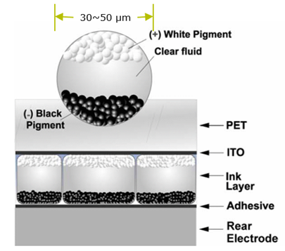
The internal structure of an EPD is as follows. There are two electrodes, with the transparent top electrode being complemented by the bottom electrode. Between these there is a thin film made up of a multitude of microcapsules, which are each approximately 30-50µm in diameter. These microcapsules contain electrically-charged pigment particles that are suspended in a fluid. Depending on the charge applied to the film, the constituent microcapsules will have their negatively-charged white pigment particles at the top (allowing them to be shown on the display) or hidden at the bottom (where they will be out of sight from those viewing the display). Conversely, the positively-charged black pigment particles will shift in the opposite direction to the white particles – so if the applied charge is reversed in certain places, the black particles can be brought to the top to create the relevant image. Different grades of grey can also be rendered as required.

Figure 1: Cross section of an e-paper display
The result of this arrangement is that detailed, high-contrast images may be created using the particles in the microcapsules. In some EPDs, a third pigment can be added (such as red or yellow) to give extra scope to the content rendered on the screen.
What really distinguishes EPDs from STNs and TFTs is their bi-stable operation. This means they only consume power when the content that they are displaying is being changed (i.e. when charge is actually applied to the pigment particles in their microcapsules). While in their steady state, they require no power. This eliminates standby current from the overall power budget of the user interface, so the battery is not being continuously drained, as with TFT/STN-based systems – power will only be mandated when the EPD’s content needs to be updated. Even then, an EPD will generally only draw a current that is at the very least an order of magnitude lower than a TFT during updates.
Advantages of EPDs over convention display technologies
Since, unlike TFT or STN displays, once an image has been rendered on an EPD screen it can be retained without any power needing to be consumed, its associated battery reserves will last much longer. This has another benefit, that should the power supply to the display be interrupted the content rendered will still be retained (whereas it would be lost from a TFT or STN). In addition to this, EPDs are able to deliver contrast levels that are far superior – making them better suited to applications where the display might be exposed to intense ambient light conditions.
In comparison to conventional displays, EPDs present a user interface solution that is much thinner and more lightweight (approximately half the weight of a TFT of equivalent size format and half the thickness too). This can be of particular merit in certain applications where there are physical constraints imposed. It should also be mentioned that, since EPDs do not emit light, user interfaces that employ them are a lot less obtrusive. This can be beneficial in certain applications where technology needs to be relatively inconspicuous when it is not actually in use – whereas conventional displays will have a constant glow emanating from them that could be distracting. Though the refresh rates are much slower for EPDs than for TFTs or STNs, fast update algorithms can be applied to accelerate this process. Also, partial localized updates mean that only the sections that specifically need it are updated. This is beneficial from both a time and also a power consumption perspective.
EPD Usage
The unique attributes of EPDs make them highly suitable for use in logistic/warehousing operations. The elevated contrast levels that can be achieved are also of great value here – meaning that information can easily be read by human operatives and automated picking systems too.
In a retail environment, it is of considerable worth too. Shelf labelling can be updated as required. This means that pricing information can be changed, discounts applied, or special offers promoted without the need to print new labels. The whole process can be managed remotely (rather than needing to have staff on the shop floor doing all the work), via a simple wireless update. Battery life is conserved, because of these EPD units’ bi-stable nature. The contrast levels that can be achieved are equally important, allowing barcode readers to scan labels without any risk of errors occurring. As well as the superior contrast, the wide viewing angles supported mean that shoppers and staff are able to check pricing information from a reasonable distance, even in non-ideal lighting situations.
There is a lot of potential for EPDs in relation to Internet of Things (IoT) applications. Here the display can be combined with energy harvesting technology (such as solar cells) so that enough electricity can be made available to apply the necessary content updates. The need to periodically replace batteries is therefore dispensed with completely.
Among the many other places where EPDs are now being utilized are home-based healthcare monitoring, building automation systems, digital signage, vending machines, cold chain monitoring devices, updatable time tables for public transport, building access systems, updatable identity badges, etc.
EPD engineering considerations when implementing EPDs into your design
TFT and STN displays are easy enough for engineers to integrate into their systems. They are usually sourced in modular form, with the controller technology, graphic processing, frame buffer etc. already built in. As all the key functionality is already included, engineers are bestowed with convenient plug-and-play solutions. When looking to design an EPD into their system, things are not quite that straightforward.
Though most engineers will be familiar with incorporating a user interface into their design that is based on a conventional display module, very few will have any prior experience when it comes to doing this with an EPD. Also, because they do not have the advantage of an all-encompassing module containing all the related electronic circuitry, many engineers have to take care of certain aspects completely from scratch.
The following points should be considered:
- Before starting to implement an EPD-based design, it will be important to ascertain whether the ambient conditions that the user interface will be deployed into are actually suitable for this approach. TFTs and STNs are backlit, generating their own illumination. Conversely, EPDs rely on the reflection of light that is incident upon them. Hence, it will not be feasible to use them in application settings where there is little (or no) available light.
- Implementation of the frame buffer that will accompany the EPD and the capacity of RAM needed for this are the next concerns. The capacity will be dependent on the size of the EPD, the complexity of the content that is being rendered, and whether monochrome or color renderings are being made.
- How to transfer the content from the frame buffer to the EPD and then refresh it then needs to be considered – so that new content can be rendered before the EPD is powered down.
- Gauging what the power budget will be is clearly vital, as this will place acute restrictions on the design. The more limited the available battery resource is, the less scope there will be from a design perspective. Once the power budget has been confirmed, it will be possible to determine what size EPD can be accommodated into the design. It will also mean the decisions can be made about what sort of updates should be employed (e.g. global, partial, fast) and how frequently such updates are done. Whether the use of a color EPD can be justified may also be established – as this will require access to more power, plus additional RAM. If this is not feasible, then a monochrome unit will be needed.
- Since they do not have a fully integrated module to work with, engineers will need to think about the overall bill-of-materials cost of their user interface design, as well as the board real estate that will be utilized. Though the passive components needed for this will be fairly negligible, the external memory resource needed could have a major impact on the overall investment required and take up valuable space too.
- What interfacing will be required is another concern. Once again, this is something that engineers simply do not have to think about when using a TFT module. SPI interface has become the standard to communicate between driver of EPD and microcontroller.
- If moving from an existing user interface system based on a TFT to one that is EPD-based, adaptations will be needed to render the content. A reduction in content complexity will probably be necessary, in order to respect the constraints of EPD. Content that was previously rendered in full color will now have to be translated into content that works in a monochrome (or limited color palette) context.
- Operational latency must also be taken into account. Engineers have to be aware of the longer refresh periods of EPDs compared to TFT or STN displays (which can be updated instantaneously). If the application is one where updates can be made overnight (such as the smart labels in supermarkets) then the EPDs will not be viewed while transitioning. In situations where a more rapid change is required, then engineers may need to consider the use of partial or fast update options to accelerate the process.

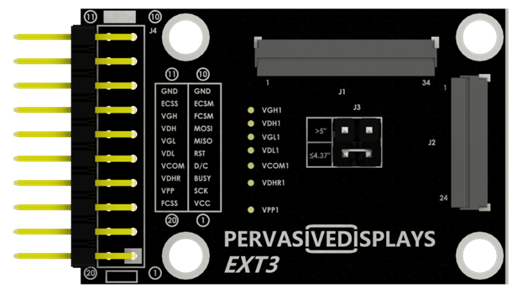
Figure 2: An example of the EXT3 extension kit now available from Pervasive Displays
Based on the need for greater visibility of all the different operational parameters before embarking on an actual EPD implementation, Pervasive Displays has introduced the EXT3 extension kit. It comprises a board with all the necessary circuitry for the display, a 1MB Flash memory, plus the exposed copper pads needed for soldering an additional external memory resource (either Flash or SRAM). A 20-way cable is also included.
This hardware offers support for the company’s complete range ultra-low power EPDs (covering everything from the 1.54-inch format right up to 12.2-inch), with both black/white and black/white/red displays covered. It is accompanied by license-free EPD driver firmware, plus an extensive software library portfolio which will help to accelerate the development process. The open-source libraries cover all the high-level demands and essential primitives (rectangles, lines, fonts, text, etc.).
Using the EXT3, engineers can get a better understanding of the operational parameters of a particular EPD and assess its suitability for their specific application. This means they are fully prepared to make important system-level decisions, rather than having to rely on guesswork.
Engineers can assess what screen size will be applicable, which host microcontroller to utilize, how much accompanying memory resource will be required, whether to go for a black/white or a black/white/red EPD, etc. They can also determine which form of update (global, fast or partial) will be appropriate.
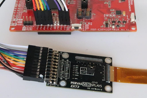
While the previous generations of EPD extension kits offered by Pervasive Displays needed a considerable number of connections, the new EXT3 requires only 8. Since the 20-way cable provided uses the standard resistor colors, it greatly facilitates identification of different signals.

Figure 3: Connection of an EXT3 extension kit to the microcontroller board via its color code 20-way cable
The EXT3 can be used with a wide array of different microcontroller boards. These include Arduino, TI LaunchPad, STMicro Nucleo, Adafruit and Raspberry Pi. By provisioning for attachment of external memory, the frame buffering aspect is straightforward to attend to – should the host microcontroller not have enough embedded memory. Depending on the size of the EPD screen, the inductance will have to be configured. This is done by simply moving the jumper. A 47µH inductance is called for when using screens that are larger than 5.0-inch, while a 10µH inductance is used for screens that are 4.3-inch or smaller.
Conclusion
Admittedly, TFT/STN displays make sense for applications where there are not any significant constraints placed on the power source, or where there is a need for constant updating of the content rendered. However, there are plenty of applications now emerging where these are simply not a viable option. This is why EPDs are now starting to see more widespread adoption. They offer a highly appealing display solution where updates are only called for relatively infrequently and where extending battery life is a priority.
By creating an effective ecosystem around EPD products – with development hardware, software libraries, drivers, cabling etc. all included – engineers will be more willing to consider EPDs for their user interface projects. The work involved will thereby be completed far quicker, with less time and resources needing to be allocated.
Category: Blog
Back to News